|
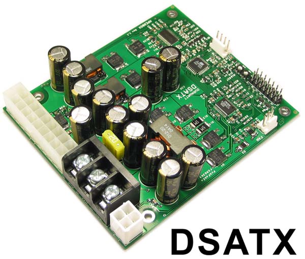
220 Watt ATX DC-DC Power Supply for
Automotive Use
DSATX Block Diagram:
DSATX Overview:
|
Specifications: |
|
Input Voltage (Operating) |
6-24 Volts Non-Regulated |
|
Input Voltage (Full Load) |
8-16 Volts Non-Regulated |
|
Input Current |
20 Amps Max |
|
Output Power |
220 Watts Max |
|
No Load Operating Current |
< 70mA |
|
Sleep Current (All Rails Off) |
< 4mA |
|
Efficiency |
> 95% |
|
Individual Supply Outputs |
Max Output Current |
|
5.0 Volts +/- 2% |
12 Amps Nominal, 13 Amps Peak |
|
3.3 Volts +/- 2% |
10 Amps Nominal, 11 Amps Peak |
|
12.0 Volts +/- 2% |
12 Amps Nominal, 15 Amps Peak |
|
5.0 Volts Standby +/- 2% |
1.5 Amps |
|
-12.0 Volts +/- 10% |
100 mA |
Right out of the box the DSATX is very easy to
use. It ships with the default easy to use configuration so
that anyone can hook it up to their car system.
Steps for Installation:
-
Connect GND, and VIN with heavy gauge wire
directly to the automotive batteries + and - terminals.
-
Connect the ATX Power Connector (J7/J8) to the
Motherboard and any peripherals to the Molex Connectors.
-
Connect a case fan with standard 3-pin
connector to J1 FAN (or assure adequate air flow).
-
Connect the ACC line to a switched 12 volt connection in the
car. (or through a switch to a constant 12 volt battery
connection). This connection does not need to be heavy gauge.
-
Connect a 2-pin jumper cable between location
G at JP1 and the Motherboards "Power On" header. This will
allow the DSATX to turn on and off the motherboard by
simulating a power button press (POLARITY MATTERS).
-
Set P1 to set the time before shutdown.
Adjustable between 0-20 minutes by default.
-
Set P2 jumper to set the low voltage cutout
voltage. To get going fast, set it to 10 volts (fully counter
clockwise). P2 is adjustable between 10-12 volts.
-
Apply 12 volts to ACC by turning on the
ignition or by flipping a switch and your ready to go!
-
Enjoy your DSATX and it's ability to power
your system, monitor for faults, and provide temperature
protection.
When your ready
to take it to the next level, the DSATX has an advanced Serial
Port Interface that allows you to connect the DSATX to a
serial port. Using a Acroname USB or RS232 translator the
DSATX can be programmed or monitored. Settings that are
programmed over the serial port stay in the memory even after
power is completely disconnected from the DSATX.
The DSATX has a
simple Character Command interface that put the DSATX into different
modes. It also has a simple programming dialog routine to set
basic configuration. The DSATX also has an advanced API for
configuring a vast range of the DSATX's control routines
allowing ultimate flexibility.
To use the DSATX's Communication
Capabilities:
-
Connect an Acroname Serial Port or USB Port
interface module (translator) to J2 of the DSATX.
-
Connect the VIN and ACC to +12 volts and connect Ground to 0
volts. (A 9v battery can also be used for offline programming)
-
Connect a cable between a Serial Port or USB
port of a Host Computer and the DSATX
-
Run HyperTerminal on the Host Computer and set
the port to 9600,8,N,1
-
The DSATX should now be spitting out
diagnostic data.
The Serial Port Accepts These Commands:
E:
Enable Writing Parameters (Allows the below commands to work)
P:
Enter Program Mode
D:
Load Factory Defaults
O:
Stop the printing of the serial diags (Feed Off)
F:
Continue the printing of the serial diags (Feed On)
Z: Set
the shutdown counter to 2 seconds (basically cause a shutdown)
@:
Force a power button press, shutdown or startup.
G:
(Advanced Feature) Get Parameter
S:
(Advanced Feature) Set Parameter
To Program the DSATX's Basic Parameters
Over the Serial Port:
DSATX is serial
port programmable! You can tell it to use the P1 P2 pots or
hard code the values into it. You must always type the
right number of characters though. IE, if you want 60
seconds, you can’t type 60. You must type 0060, etc. You
don’t hit return when your done typing in the values. It
will automatically take it. If you mess up, make sure you do
it again and get it right..
-
Type
"E" and answer "Y" to enable the P command to work.
-
Type "O" to turn off the Diagnostics so they
don't clutter the screen
-
Type "P" to enter Program Mode
-
Answer the questions that follow:
-
If you answer "y" to Use Pots, the DSATX will
use the P1 and P2 POTs to set the Main Countdown Timer and the
Low Voltage CutOut.
-
MAXTIMER1 is the maximum amount of time in
seconds that P1 will be able to set.
-
If you answer "n" to Use Pots, the DSATX will
remember you hard coded values that you set for the Main
Countdown Timer (TIMER1) and the low Voltage Cutout (LOWVOLTS)
-
You must enter 4 digits for LOWVOLTS and
TIMER1. IE: 1150 = 11.50 volts and 0600 = 600 seconds.
-
VTURNON is a feature where the DSATX will not
turn on the computer until after the Engine is Running.
-
Type "F" to put the DSATX back into Automatic
Diagnostic Feed mode.
Here is an example of the basic programming
interface:
In the below
example, we program the DSATX. Tell it to use the Pots (P1,P2)
for the Timer1 Timer and the low voltage threshold cutout (P2
selects a value between 10 and 12 volts). Maxtimer1 is the
maximum seconds you can set with the P1 Pot. Basically, if you
set the pot half way and had Maxtimer1 set to 1200, it would
shutdown in 600 seconds. If you set the Maxtimer1 to 0060 you
would have between 0 and 60 seconds to select with the P1 Pot.
VTURNON is an
option where ACC has to be high and the engine has to be
running before the computer will turn on.
|
P
PROGRAM MODE
Use POTs? y/n
y
MAXTIMER1:
1200
VTURNON? y/n
n
PROGRAM DONE
|
< Type the letter P
< Type the letter y
< Type 1200 (Must type 4 characters)
< type the letter n |
In the below
example, we program the device. Tell it to Hard code the
values for the Timer1 Timer and the low voltage threshold. If
you set Lowvolts to 1050, the unit wouldn’t shutdown until it
hit 10.50 volts on the VIN input. If you set Timer1 to 0600,
then after 600 seconds of ACC going away, the computer would
turn off.
|
P
PROGRAM MODE
Use POTs? y/n
n
LOWVOLTS:
1050
TIMER1:
0600
VTURNON? y/n
n
PROGRAM DONE
|
< Type the letter P
< Type the letter n
< Type 1050 (Must type 4 characters)
< Type 0600 (Must type 4 characters)
< Type the letter n |
DSATX Diagnostic Data:
Serial Port Diagnostic data takes this form
(Data will flow out every 200ms):
+030.3:12.56:12.00:05.19:03.34:10.49:0560:YNYY:3:0558
A : B : C : D : E : F : G : H :I: K
A: Temperature in Degrees C
B: Input voltage at VIN
C: 12 Volt Rail Output
D: 5 Volt Rail Output
E: 3.3 Volt Rail Output
F: Low Voltage Threshold (P2 Adjusts this)
G: Number of Seconds for main Shutdown Timer (P1 Adjusts this)
H: Y/N Good/Bad(Vin Voltage Good, Acc Pin High, Temp Good,
PS_ON Asserted)
I: State of
SDC:
(0: off, 1:Pulse, 2: Running, 3: Count Down,
4: Shut Down)
K: Count value for Shutdown Counter (seconds)
DSATX
LED Codes:
OFF = System off / sleep mode
ON = Running Mode, the computer runs/boots in this mode
1 blinks = main countdown timer
2 blinks = shutting down (after shutdown pulse is sent)
3 blinks = N/A
4 blinks = Over or Under Temperature Condition. (Are you using
a fan?)
5 blinks = Power Supply Overload or Fault.
DSATX Connections:
Communication Port Memory Map (Advanced
Feature):
Contents:
1:
DSATX 220 Watt ATX DC-DC Power
Supply
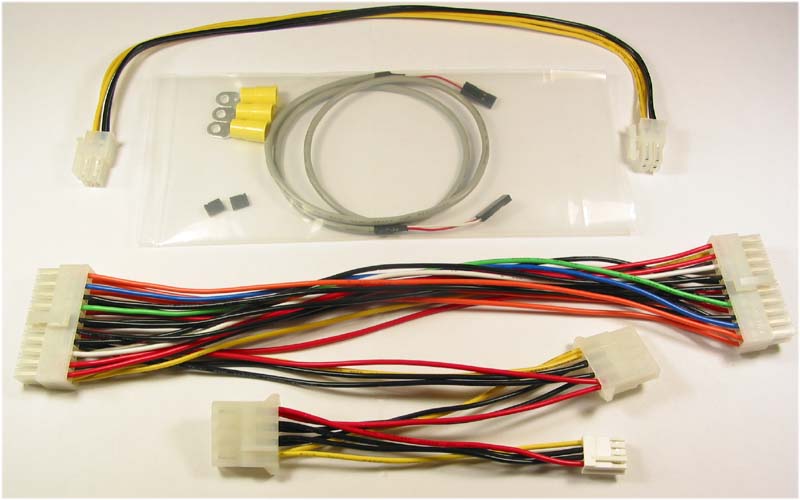
1:
DSATX Cable Kit:
1 : 9" 20pin ATX Power Cable with 2 HDD Power Connectors and 1
Floppy Connector
1 : 12" 4 pin ATX 12V Power Cable (CPU Power Cable)
2 : 0.1" Shunt Jumpers
1 : 24" 2-pin to 2-pin MotherBoard Power Switch Cable
3 : Insolated Terminal Ring Crimp/Solder Connectors 12-10AWG
1:
DSATX User Guide
For more info on the DSATX,
look in this directory
Product
Support Forums
|

